Interactive Site Plans🔗
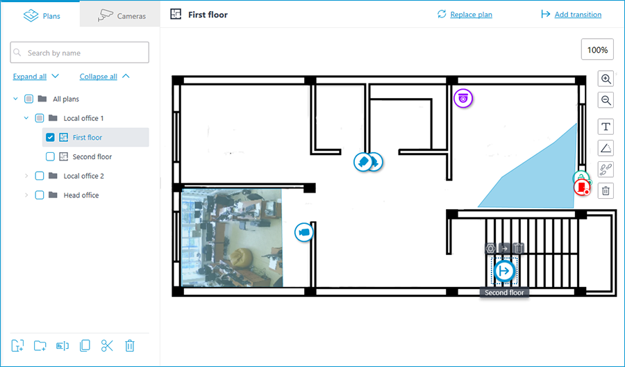
To set up camera layout in the Eocortex Configurator application, go to  Plans tab.
This tab contains site plans and the cameras, sensors, relays placed on these plans, as well as camera fields of view and transition points between the plans.
Selecting the Camera placement tab opens a camera tree with the relevant elements.
Plans🔗
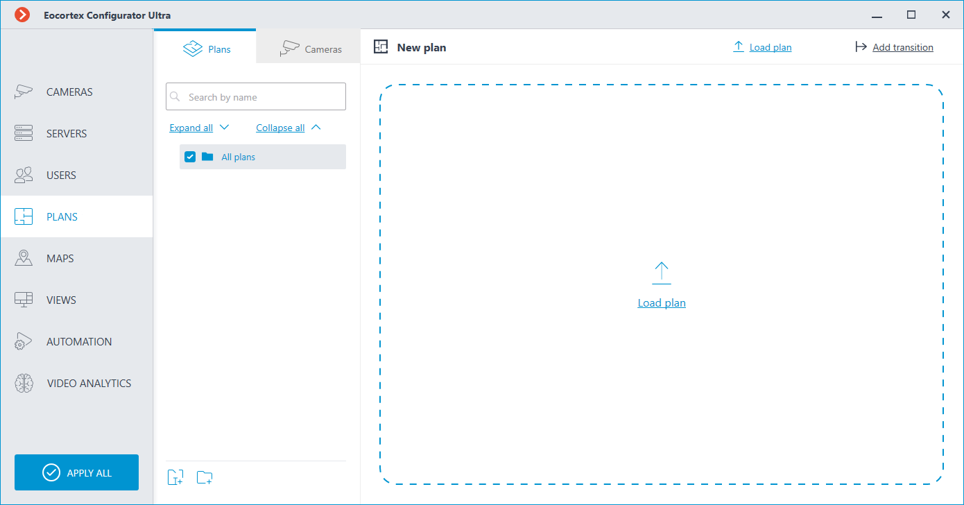
By default, the plans tree is empty. To add a plan, click the Add plan button in the middle of the screen, or find it in the context menu or on the bottom panel of the plan tree.
Then, it is needed to click the  Load plan button.
Note
Supported image formats: svg, jpg, bmp, png, gif, tif.
After adding a plan image it is possible to:
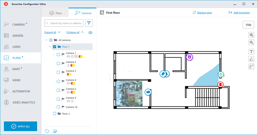
 Replace plan: allows to upload a new background image to replace the previous one in the plan.
 Add transition: allows to add to the plan a transition point, by clicking which the user will be able to go to the plan associated with this point.
If a transition point is placed on the plan, but not configured, its icon will be red:
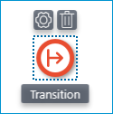
To set it up, place the transition point to the plan and click the  button.
In the Transition settings window that opens, select the plan to which the transition should guide to. In the Distance between links, min: field, set the time in minutes that a person would actually spend following this transition, and then click the Apply button.
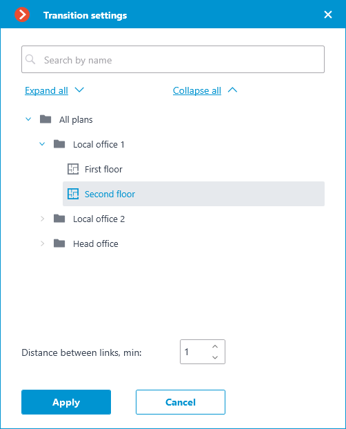
The plans window will automatically switch to the specified plan, and a transition endpoint will be added in the center of the screen. Place it on the plan in a location that actually connects this plan to the previous one.
When selecting the icon of the configured transition on the map, the transition button becomes available. It allows to quickly switch between the plans. When switching, the new plan will open in such a way that the transition endpoint icon will be located in the center of the screen.
A bar with the following buttons is available on the right side of the plan:
 Zoom in: Scales the plan up.
 Zoom out: Scales the plan down.
Note
You can also use the mouse wheel to change the scale of the plan.
 Show camera names: Hides or displays the names of all cameras on the plan.
 Show fields of view: Hides or displays the field of view of all cameras on the plan. If no fields of view are configured, this button will not be displayed on the panel.
 Show heat maps: Overlays a heat map for the specified period on the video in the camera's field of view. If there are no cameras with the Traffic Density Heat Map module configured, this button will not be displayed on the panel.
The following actions become available in the context menu and on the bottom panel of the plans tree when selecting a folder or an individual plan on the left panel:
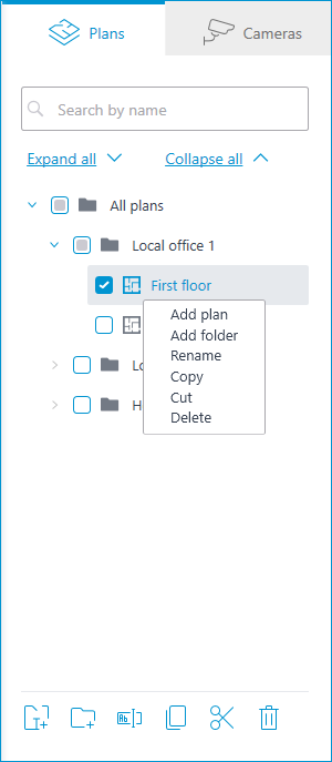
In addition to selecting a plan manually, it can also be found using the search field above the plans tree.
It is possible to move between folders both individual plans and even entire folders.
Warning
Plan, starting from Eocortex 4.1, is the lowest level element in the tree. When migrating settings from earlier versions, folders are used to keep the hierarchical structure. For an item with attachments, a folder with the same name is created at a higher level, in which the item itself and its attachments are placed in the same manner.
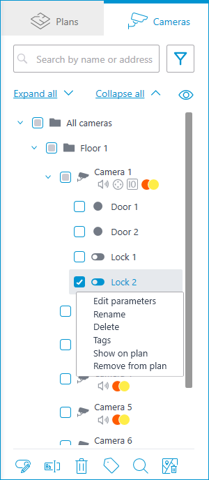
Cameras🔗
General🔗
This tab contains the cameras tree.
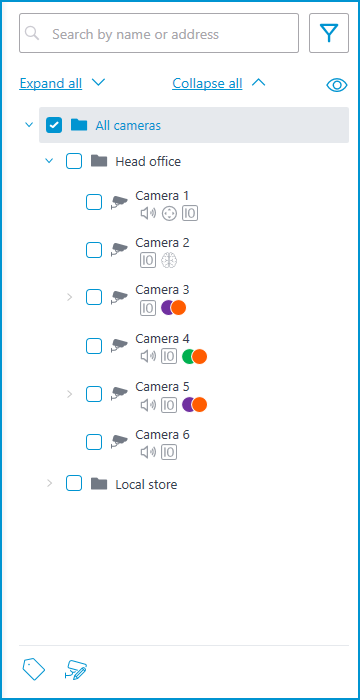
Cameras can have the following attributes:
 : the camera has enabled video analytics module;
 : the camera has enabled sound receiving option;
 : the camera has enabled PTZ;
 : the camera has enabled alarm inputs/outputs.
Colored labels: the camera has tags with the displayed colors;
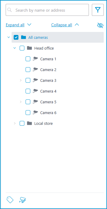
If necessary, you can hide the attributes by clicking the  icon on the right side of the tree.
Hovering the cursor over the camera opens a preview window that contains video from the camera and a list of its attributes.
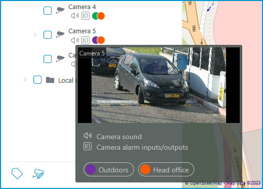
The same preview window opens when hovering the cursor over a camera located outside the cameras tree.
To select a camera manually, you can also find it by name or IP address using the search field above the camera's tree.
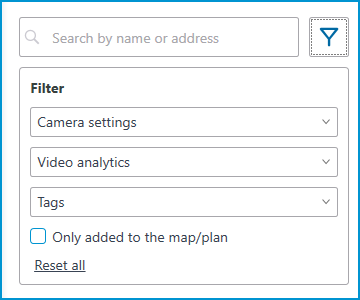
You can filter cameras by clicking the  icon and customizing the following filter options:
Camera settings
Filter by the following attributes: , , .
Video analytics
Tags
Note
The availability of filtering options depends on the settings of the cameras. Filtering applies immediately after selecting an item.
Warning
For placed sensors and relays, filtering only works for the Only added to the map/plan parameter.
If necessary, it is possible to collapse the filtering by clicking the filter button. When the filtering is applied and collapsed, the filter icon changes to  .
.
Representation of the camera on the plan🔗
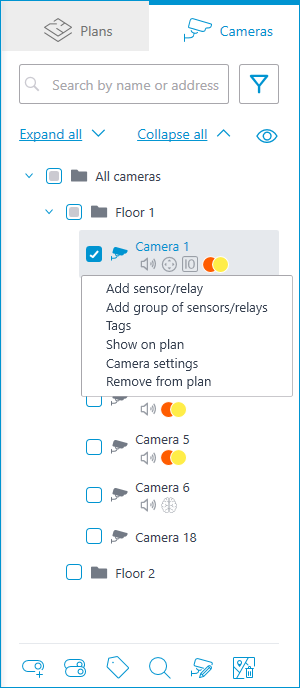
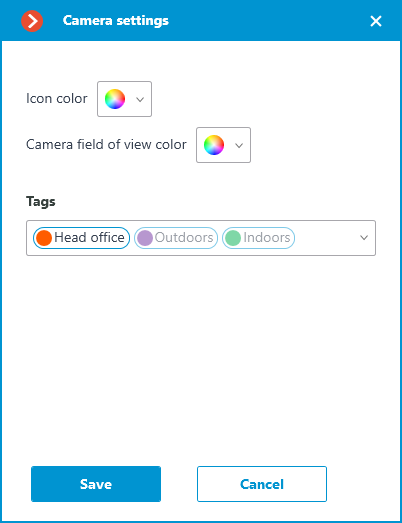
To customize the camera representation, click Camera settings in the camera context menu or at the bottom of the camera tree.
The following can be configured in the camera settings window:
Color of the camera icon
Color of the camera field of view
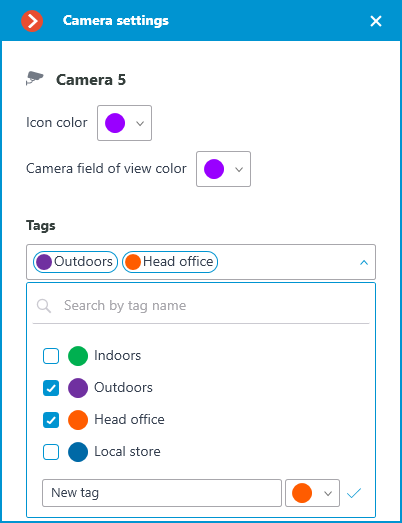
This settings window is available both for individual cameras and for entire groups. When opening the settings window for a group of cameras at once, the own settings of cameras are displayed in the combined view. If the camera settings are the same, the actual parameter values will be displayed for the group. Otherwise, merged information is displayed.
Placement of cameras on the plan🔗
General🔗
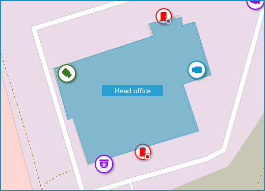
To add a camera to the plan, drag it from the camera tree to the needed point on the plan.
The camera icon depends on the settings you set in the Cameras section. If PTZ functionality is enabled for a camera, it will be displayed on the map with the corresponding icon. Other cameras are displayed with the usual icon.
When a camera is selected on the map, the following buttons appear around it:
 : view video from the camera in full-screen mode.
- : edit camera settings.
 : remove the camera from the map.
 : rotate the camera.
- : set up the field of view.
 : jump to the camera position in the tree.
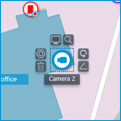
Note
Also, when a camera is selected, its name will be displayed. By default, it is hidden.
Camera field of view🔗
If necessary, a custom field of view can be created. To do this, click the button. After that, an editable rectangle will appear, which can be used to adjust the needed viewing angle. The shape of the field of view can be changed indefinitely: add and delete nodes, move them along the plan or the map.
To delete a custom camera field of view, select it and click the button. If the video displaying has been set in the field of view, deleting the FOV deletes this setting as well.
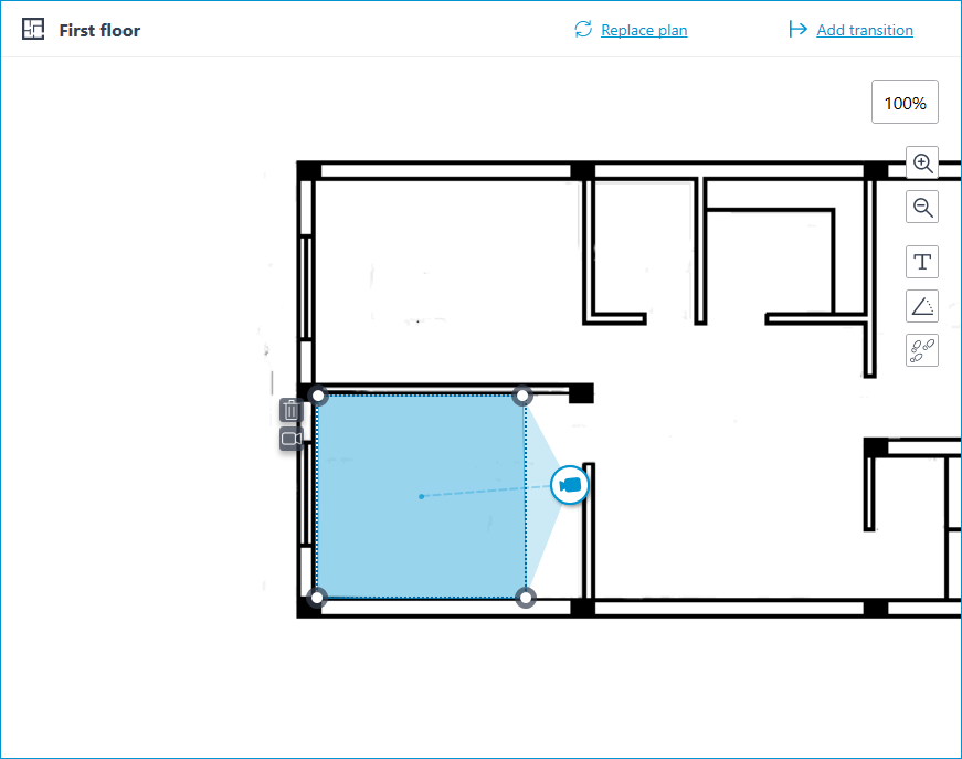
Video inside the field of view🔗
The field of view can display video from the camera. To set it up, click the  button. This will create an editable rectangle in which the live video from the selected camera will be embedded. By default, video appears as the size of the dotted outline of the field of view.
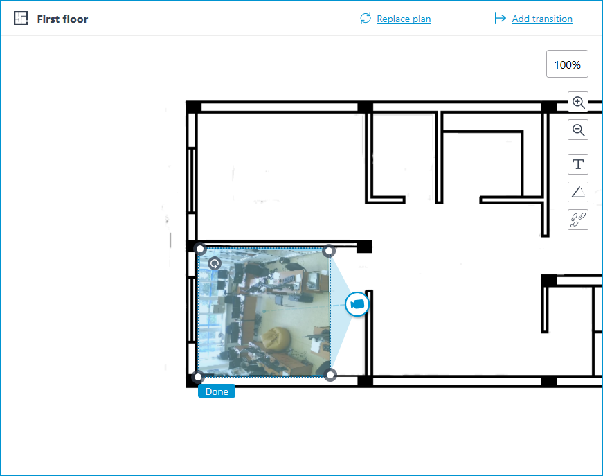
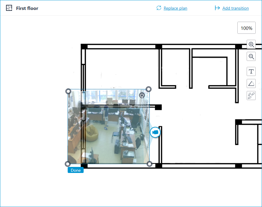
Adjust the shape and location of the displayed video so that the area visible in the frame matches its position on the map. Once ready, click the Done button.
To edit an already configured video displaying, click the  button. To reset the video displaying settings in the field of view, click the crossed-out camera button. Reconfiguration of the video displaying after resetting will be performed according to the current shape of the field of view.
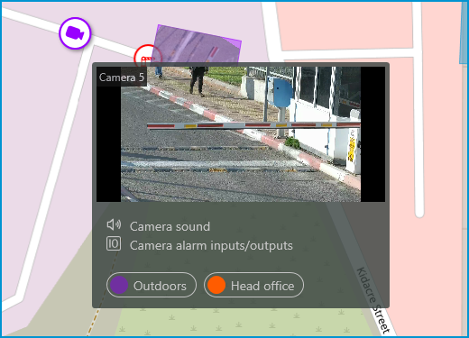
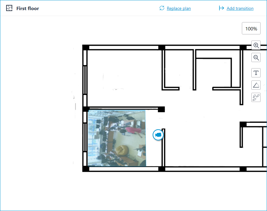
When the field of view editing mode is switched off, the video will be cropped according to the shape of the field of view:
Placement of sensors and relays🔗
If the camera has alarm inputs/outputs enabled in the Cameras section, sensors and relays connected to it can be placed to the map.
To place a sensor or a relay, select the Add sensor/relay item in the camera context menu or click the corresponding button in the bottom panel of the cameras tree.
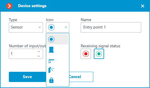
The following sensor parameters can be configured in the Device settings window:
Type
Sensor
Relay
Displayable icon
Default icon
Door
Barrier
Turnstile
Lock
Name
Number of input/output
Receiving signal status
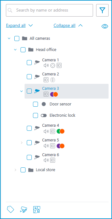
Sensors are displayed in the camera tree for those cameras to which they are connected. The device type and name of the sensor are also displayed there.
To create a sensor or relay group, click Add group of sensors/relays in the camera context menu or at the bottom of the camera tree.
In the Add group of devices window, all the same parameters can be selected that are available when setting up an individual sensor. But the difference is that in this case, several I/Os can be specified simultaneously.
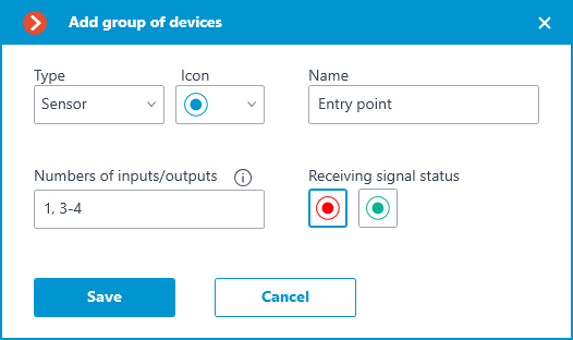
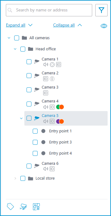
After clicking the Save button, all sensors/relays will be added to the associated camera. The device name will be generated from the sensor name and the input number.
If the sensor is placed to the plan, the following additional items appear in its context menu:
Show on plan
Remove from plan
The sensor will be displayed on the map with the icon that was selected when it was created. The device type will also be displayed. The color of the sensor depends on the specified state when there is a signal and, consequently, on the current signal status for this sensor.
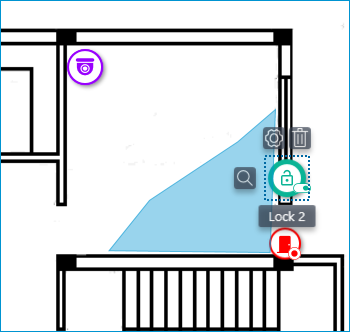
When the sensor is selected on the map, its name and the following buttons appear: Edit parameters, Remove from map, and Show in tree.
Grouping devices on the plan🔗
When you change the scale of the plan - cameras, sensors, relays, and transitions are grouped into markers.
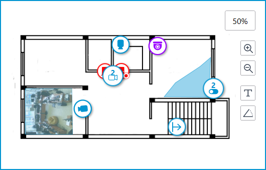
Elements of the same type located close to each other on the plan are grouped into one marker with the number of devices and their type: camera, sensor, relay, or transition.
Elements of different types are grouped into one marker with the number of devices.
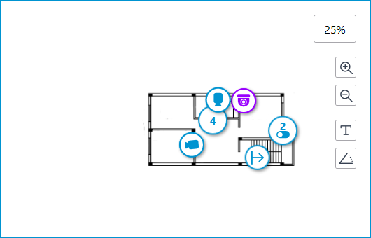
Note
If the number of grouped elements is more than 99, the number on the marker will be displayed as 99+.
Heat maps🔗
To use heat maps, enable and configure the Traffic Density Heat Map module in the Analytics section.
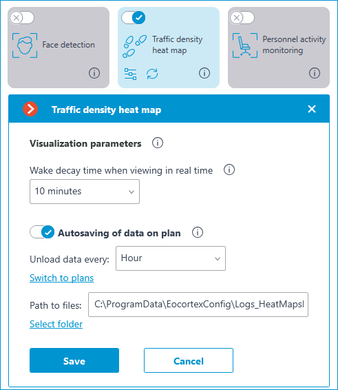
For the Autosaving of data on plan function of the Traffic Density Heat Map module to work, the field of view must be configured for the camera placed on the plan in the Plans section.