Integrations🔗
To set up the integration of Eocortex video surveillance system with the external systems, it is required to go to the  Automation tab in the Eocortex Configurator application, select an individual camera in the camera tree, then, on the opened page, go to the Integrations tab.
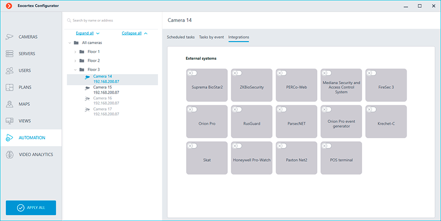
On the tab, it is required to enable the integration with the required system using the  switch, then set up the integration by clicking the
  button.
Honeywell Pro-Watch🔗
The connection to the Honeywell's Pro-Watch® comprehensive security platform can be adjusted on the Connection tab.
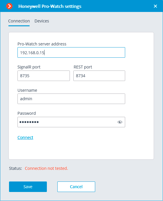
The connection setup parameters:
Pro-Watch server address: the IP address of Honeywell's Pro-Watch® server.
SignalR port and REST port are the ports that are used to provide Honeywell's Pro-Watch® API. The default parameters of these ports correspond to the default parameters of Honeywell's Pro-Watch®.
Username and Password are the name and Web password of the Honeywell's Pro-Watch® user for whom the access to the Honeywell's Pro-Watch® API service has been set.
After setting up the connection, it is required to test it by clicking on the Connect link. In case of a successful test connection, the list of Honeywell's Pro-Watch® system devices will become available on the Devices tab.
In this list, it is required to mark the devices whose events will be displayed and registered in Eocortex.
ONVIF Profile A/C🔗
There are two tabs available in the integration settings:
General settings
Integration of face recognition
General settings🔗
The General settings tab is used for system configuration of connection to the external system.
The following settings are available:
Server address: IP address or domain name. There is no need to specify a prefix with the name of the protocol (http://, etc.). There is no option to use a secure connection (HTTPS).
ONVIF port: The port of the external system.
ONVIF login and ONVIF password: Login and password to connect to the external system via ONVIF. These credentials are usually not the same as the system users and are specified in a separate section of the external system settings.
After finishing the setting, press the Connect button.
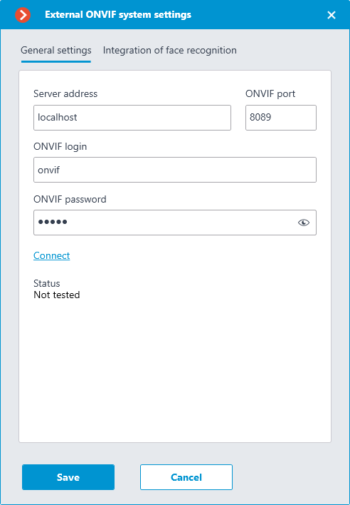
The Status field displays the result of the check:
Not tested.
Testing...
Connection succeeded.
Server is unavailable: In this case, check the network availability of the external system server and its ONVIF settings.
Request timeout: In this case, check the network availability of the external system server.
Unknown error: More detailed information about such errors can be found in Eocortex log files that can be sent to technical support for analysis.
Verification integration🔗
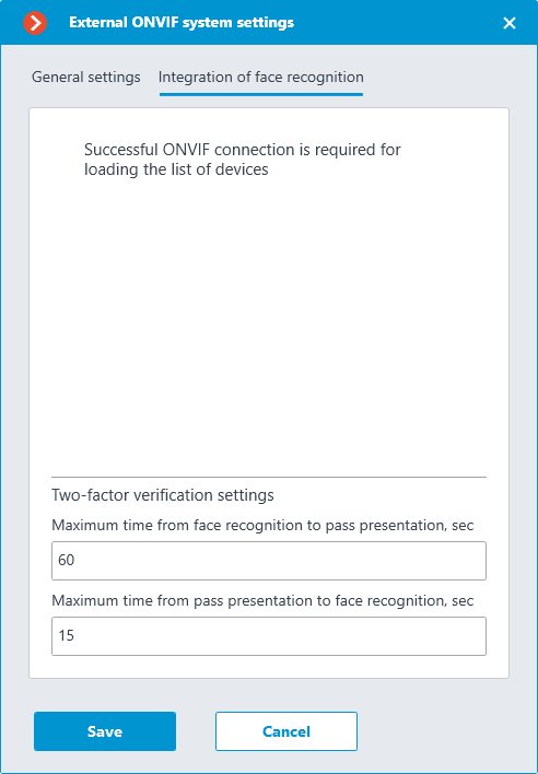
On the Integration of face recognition tab one-factor and two-factor verification are configured for the devices from which events are to be received for the configured camera.
Note
The list of devices is displayed only after successful connection testing on the General settings tab.
The following folders are displayed in the device tree:
One-factor authentication: Devices configured for one-factor verification mode.
Two-factor authentication: Devices that support two-factor verification.
Note
Even though cameras can only use one verification mode, there is no restriction on connecting devices of both types.
Below the device tree are the Two-factor verification settings.
Maximum time from face recognition to pass presentation, sec: The maximum time interval from employee recognition to badge reading. It is not recommended to set this value too high, because after successful recognition the employee may leave the access point, and the badge may be presented by someone else.
Maximum time from pass presentation to face recognition, sec: The maximum time interval from badge reading to recognition. For example, in situations where an employee approached the access point wearing a mask and only removed it after presenting the badge.
The synchronization of the database used by one of the Eocortex recognition modules with the database used in the external system is configured in the Eocortex server settings.
Paxton Net2🔗
The following tabs are available in the integration settings:
General settings;
Camera settings.
General settings🔗
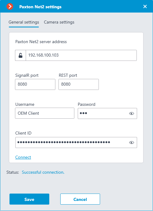
The General settings tab is used for setting up the connection to the Paxton Net2 ACS server.
To configure the connection, specify the following parameters:
Paxton Net2 server address: IP address or domain name of the Paxton Net2 server
SignalR port: Paxton Net2 server connection port
REST port: Port for sending REST API requests to the Paxton Net2 server (usually the same as SignalR)
Username: Name of the Paxton Net2 account used for connection
Password: Password of the Paxton Net2 account used for connection
Client ID: Identifier contained in the Paxton Net2 license filename
To test the connection with the provided settings, click the Connect button. The Status section will display the result of the test.
If the connection is successful, further settings should be made on the Camera settings tab.
Camera settings🔗
The Camera settings tab is used for setting up the registration of events from Paxton Net2 objects in Eocortex.
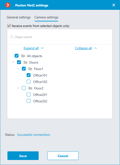
To receive events only from certain objects, enable the Receive events from selected objects only: option and check the selected objects.
If the Receive events from selected objects only: option is disabled, Eocortex will register all Paxton Net2 events as related to the selected camera.
Warning
Eocortex registers events for the camera independently of the settings of other cameras, so the same Paxton Net2 object can cause the reaction of the system and create an entry in the Events Log for multiple cameras simultaneously.
BioStar 2🔗
The following tabs are available in the integration settings:
General settings🔗
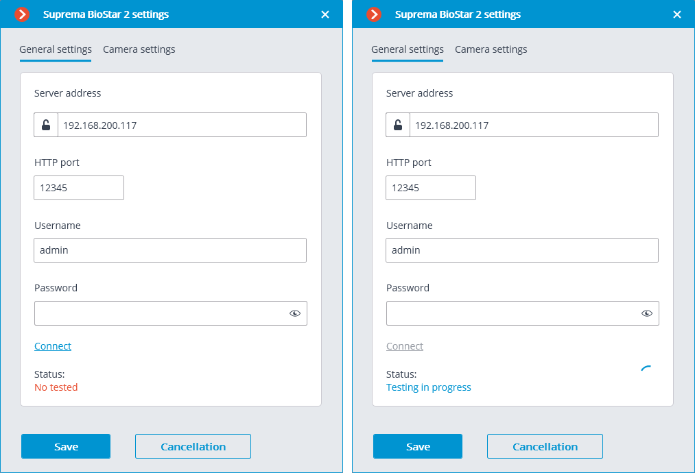
The General settings tab contains the settings for a network connection to the BioStar 2 ACS for the whole system.
The following settings are available:
Server address: IP address or URL of the BioStar 2 server. Prefixes, such as http://, are not required to be specified in this field. To enable a secured connection via HTTPS, click the
 button.
HTTP port: HTTP(S) port of the BioStar 2 server. Interaction with the ACS utilizes the HTTP and WebSocket protocols, but both protocols use the same port. The WebSocket port can be configured individually in BioStar 2 settings, but it is not necessary to set it in the integration settings.
Username.
Password.
When all settings are done, click the Connect button.
Note
The connection test result will be displayed in the Status field.
Camera settings🔗
The Camera settings tab contains settings from which devices the system should receive events for this camera.
Note
By default, all ACS events will be received from all devices.
If the integration is enabled on multiple cameras with the default settings, the events will be duplicated for all enabled cameras.
There are 2 types of BioStar 2 objects available for configuration:
 Doors. A high-level object that is most often configured with rules in BioStar 2. Usually the door is connected to a relay and a sensor of other device. Receiving events from specific doors allows to configure the integration more precisely;
 Devices. A lower-level BioStar 2 object. Setting up to receive events from the device allows configuring the integration more flexibly. For example, if BioStar 2 is in the deployment phase, the list of doors and their properties will continuously change. When configuring to receive events from the specific door, it will be necessary to change the integration settings each time when something has changed. But when configuring to receive events from a device, when new doors are connected to the device, the integration settings would not need to be changed.
ZKBioSecurity🔗
Two tabs are available in the integration settings:
General settings;
Camera settings.
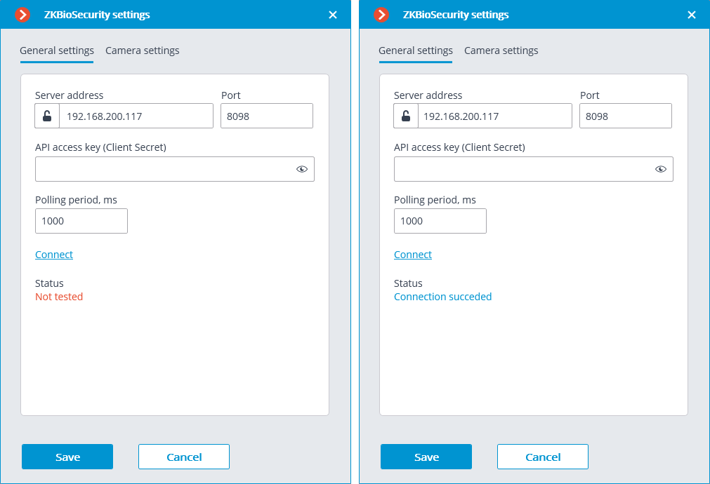
General settings🔗
The General settings tab is used to configure the system-wide connection to ZKBioSecurity.
Note
Setting up the connection to only one ZKBioSecurity server is available per one server system.
The following settings are available:
Server address (IP address or URL. Prefixes as http:// are not required to be specified in this field).
Use of a secure connection can be set here.
Port. Interaction with ZKBioSecurity is performed via HTTP.
API access key (Client Secret).
After making the settings, it is required to press the Connect button.
Note
The Status field will show the verification result.
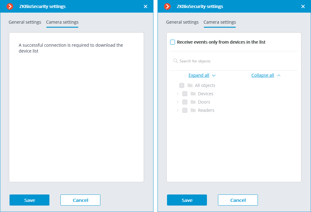
Camera settings🔗
On the Camera settings tab, it is possible to specify the devices whose events are to be received for the given camera.
Note
By default, all the ZKBioSecurity events are received from all devices.
Note
Enabling integration on multiple cameras with the default setting will provide duplication of the events for all enabled cameras.
Three types of ZKBioSecurity objects are available for configuration (full text search is available):
Doors
 . A high-level object whose rules are usually configured in ZKBioSecurity. Usually, the door is connected to a relay and a sensor of some device. Receiving events from specific doors allows for a more precise integration.
Readers
 . A high-level object whose rules are usually configured in ZKBioSecurity. Typically, the reader is installed on doors, turnstiles and other access control points. Receiving events from specific readers allows to configure the integration more precisely.
Devices
 . A lower-level ZKBioSecurity object. Setting up the reception of events from the device permits to configure the integration more flexibly. For example, if multiple doors are connected to the same device and ZKBioSecurity is in the process of being set up, and the doors are being connected and disconnected, the integration settings will have to be changed frequently when setting up the reception of events from the specific doors. In the process of configuring the reception of events from a device, the integration settings do not need to be modified when new doors are being connected to the device.
Note
Changing the names of ZKBioSecurity objects (devices, doors or readers) requires their manual reassignment in the device list every time. Otherwise, the events from the newly renamed object will not be registered.