Requirements and recommendations for the License plate recognition (Complete) module🔗
Tip
To calculate the parameters of the server and client hardware on which you plan to run Eocortex software, use our Calculator.
Important
If multiple video analytics modules are used on a single camera, it should be installed and configured to meet the requirements of all modules.
For example, module A and module B are used on the camera with the following requirements:
Module A: Camera tilt angle to the plane is at least 10°; resolution is at least 1024×768; frame rate is at least 20 frames per second.
Module B: Camera tilt angle to the plane is no more than 20°; resolution is no less than 1920×1080; frame rate is no less than 6 frames per second.
In this case, the camera must be installed and configured in order to comply with the following conditions:
Camera tilt angle to the plane is from 10° to 20°; resolution is at least 1920×1080; frame rate is at least 20 frames per second.
Warning
The module works only with 64-bit version of Eocortex.
For the proper operation of the module, it is imperative to correctly select, place and set up the camera, adjust the software motion detector and the module itself. When choosing the camera, it is recommended to consider the image quality requirements, control zone particularities, and the conditions of the camera installation and operation.
Requirements to the license plate image🔗
It is assumed that the license plates of the vehicles to be recognized correspond to the requirements of the Vienna Convention on Road Traffic (Part I: Convention on Road Traffic – Attachment 2), in particular:
“2. The registration number shall be so composed and displayed as to be legible in normal daylight at a distance of at least 40 m by an observer placed on the axis of the vehicle, the vehicle being stationary ...”
“3. When the registration number is displayed on a special plate, this plate shall be flat and fixed in a vertical or nearly vertical position and at right angles to the vehicle's median longitudinal plane”.
The license plate number will be recognized only if its image is rich in contrast and fits entirely in the frame.
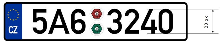
Additionally, there is a requirement regarding the minimum height of a symbol on the image of the license plate in the frame (i.e. the height at which it is still possible to provide recognition): 30 pixels. This limitation is illustrated on the picture below. You can also see the minimum permissible dimensions for the license plate of Ukraine and Russia (the overall width is given for reference because it may help when calculating the focal length).
Note
When the camera is installed outside, the natural noise pollution of the video image may happen due to the unfavorable weather conditions (rain, snow). In order to improve recognition in such circumstances, it is advisable to increase the size of the license plates in the frame.
Recommendations on camera installation🔗
In this section you will find the recommendations on camera installation that need to be followed in order to ensure the reliable recognition of license plates in the control zone. Each installation location has its individual characteristics. This section contains the typical camera installation diagrams. They are to be taken into consideration at the stage of designing the traffic video surveillance systems with due account for the specific parameters of the site.
The correctly performed installation must ensure the following:
The license plate image in the frame must correspond with the requirements specified in the previous section;
The maximum duration of presence of the license plate in the frame.
It is also necessary to fulfill the following requirements listed below (both for highway and checkpoint installation locations).
To minimize the occurrence of false triggering in the process of recognition, it is imperative to install the camera in such a way as to avoid the presence of the high-contrast objects in the frame, for example, billboards, trees, grille fences etc.
In order to avoid camera flaring, it shall not be directed at the light sources (the Sun, streetlamps) and at the highly reflective objects.
To prevent the distortion of the symbols on the license plate image, it is advisable to ensure the optimal camera installation angles. When performing the surveillance on descending or ascending vehicles, the road inclination angle must also be taken into consideration.
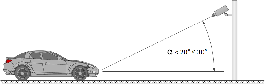
Vertical camera angle🔗
Recommended: up to 18–20°
Maximum permissible: 30°
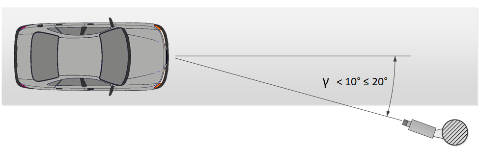
Horizontal camera angle🔗
Recommended: up to 5–10°
Maximum permissible: 20°
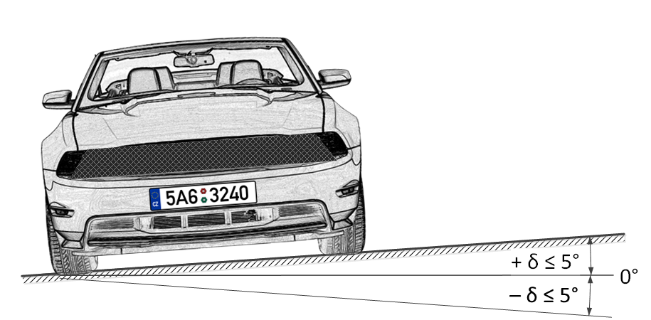
Permissible banking angle🔗
In the course of the installation, it is required to ensure that the tilt of the license plate on the image in relation to the horizontal plane of the camera does not exceed 5° both clockwise and counterclockwise. When recognizing the single line numbers with no more than six symbols it is possible to check the appropriateness of the selected camera tilt angle using the “single line rule”: the imaginary horizontal line must cross the first and the last symbols of the license plate.
The distance from the camera installation location to the beginning of the viewing zone is determined by the focal length of the lens. And conversely, if the distance from the camera installation location to the center of the control zone is known, it is required to ensure the appropriate focal length of the lens.
When using the separate IR illuminator, the angle of the infrared light must correspond to the camera viewing angle. The correspondence of the IR illuminator beam angle and the camera lens viewing angle is especially important at the large distances, when the camera operates at the limit of its sensitivity.
The typical camera installation diagrams for license plate recognition are given below.
Camera on a checkpoint🔗
When performing video surveillance of the entrances and exits of the protected areas, the speed of the vehicles normally do not exceed 20 km/h, meaning that it is possible to use the license plate recognition module in the Parking mode. In this case, the camera is normally installed at the edge of the lane.
The camera installation height shall be above the level of the headlights of the vehicles.
The distance between the place of installation and the focus area must be at least 3 meters.
The installation of the camera in close proximity to the prospected license plate detection area and the usage of the short focus lenses lead to the depth of field reduction and the distortion of the image at the edges. Both must be avoided to ensure reliable recognition.
For the separate control of the exits and entrances, it is recommended to install separate cameras, one on the entrance and the other on the exit. When only one camera is used, the vehicles traveling in the opposite directions may block one another. Moreover, it is advisable to separate the traffic lanes not only with road marking, but also with a barrier, where the width of the road allows it.
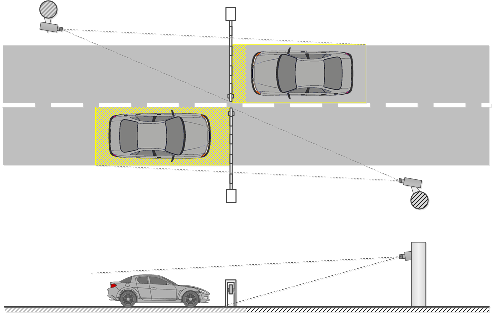
When using the rising arm barrier, the controlled area may start immediately before it. In this case the camera is to be installed at a distance from the barrier line.
Controlled areas with separate lanes and a rising arm barrier
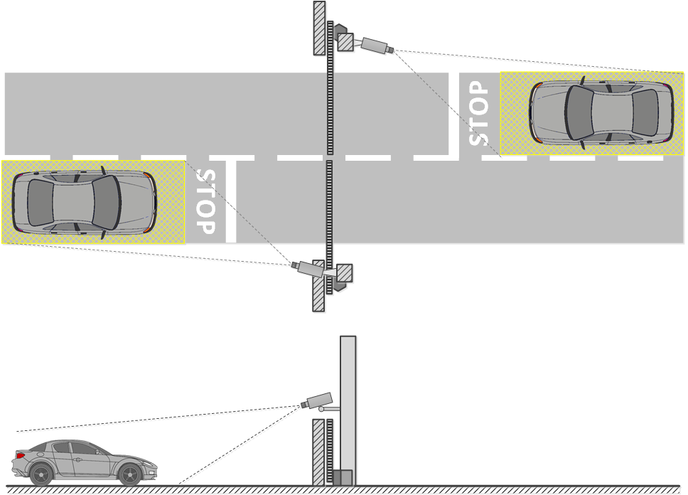
When using the gates, the controlled area must not start immediately before the gates, because the camera is usually installed at the level of the gates. In such a case a stop line, a mandatory stop sign or a traffic light is used for stopping the vehicle in the controlled area.
Controlled areas with separate lanes and gates
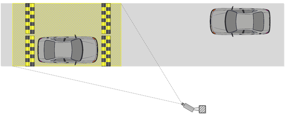
At the unregulated crossing points it is required to use speed bumps (road humps) to make the drivers reduce speed to ensure successful recognition; it is also advisable to use additional means such as the speed limit signs (up to 5 km/h), mandatory stop signs, stop lines etc.
Open controlled area with two-way traffic
The suggested camera installation parameters for surveillance of exits and entrances calculated for the cameras with the sensor size of 1/3" are shown in the following table. These parameters allow to provide the minimum distance between the camera installation location and the controlled area of the given width. It is also required to be guided by the quality of the license plate image in the focusing area in the course of the installation.
Sensor size: 1/3" |
||||||
|---|---|---|---|---|---|---|
Installation height (m) |
1 |
1,5 |
2 |
2,5 |
3 |
4 |
Area width: 3 m |
||||||
Vertical angle, ° |
18 |
25 |
30 |
30 |
30 |
30 |
Focal distance (mm) |
5 |
5 |
6 |
7 |
8 |
11 |
Near zone (m) |
1,3 |
1,6 |
1,9 |
2,6 |
3,5 |
5 |
Focal zone (m) |
3,1 |
3,4 |
3,5 |
4,3 |
5,2 |
7 |
Far zone (m) |
∞ |
20 |
8,5 |
9 |
9,6 |
10 |
Area width: 6 m |
||||||
|---|---|---|---|---|---|---|
Vertical angle, ° |
9 |
14 |
19 |
23 |
28 |
30 |
Focal distance (mm) |
5 |
5 |
5 |
5 |
5 |
6 |
Near zone (m) |
1,7 |
2,2 |
2,5 |
2,7 |
2,7 |
4 |
Focal zone (m) |
5,7 |
6 |
5,8 |
5,9 |
5,6 |
7 |
Far zone (m) |
∞ |
∞ |
∞ |
44 |
21 |
17 |
Note
The parameters shown in the above table are indicative. It is strongly recommended to calculate the camera installation parameters individually, using the CCTV calculator, with due regard for the design and operational characteristics of the particular cameras and their working environment.
Camera on a highway🔗
When organizing the surveillance on a highway, the camera is normally installed on an L-shaped pole at the edge of the lane or on the arch support above the center of the lane.
The standard installation height is 4 to 6 (maximum 20) meters.
The vertical camera tilt angle is regulated by the basic guidelines.
The distance to the controlled area and, correspondingly, the focal length of the lens are determined based on the camera installation height, tilt angle and width of capture.
The higher the camera is installed, the higher is the probability that the license plates of the vehicles moving at a small distance from one another (for example, in case of a traffic jam) will get into the frame. But it needs to be noted that the increase of height leads to the higher distortion of the license plate images, and the symbol size may be close to the permissible minimum (or may even be unacceptable). In such cases it is possible to shift the region of interest to the higher distance by reducing the camera vertical tilt angle and changing the focal length in order to ensure reliable recognition.
The modern IP cameras are capable of covering several (up to 4) traffic lanes. Thus, it is possible to reduce the quantity of cameras to be installed in the controlled area. But in this case it is required to choose the installation height, tilt angle, and focal length in such a way as to minimize the optical image distortion (for example, the short focus lenses give significant image distortion on the periphery of the frame).
In the table below you will find the approximate parameters of camera installation for performing video surveillance on a highway. The camera parameters used for the calculation are as follows: 1/3" sensor and 5-50 mm varifocal lens. The values shown in the table allow to provide the minimum distance from the camera installation location to the controlled zone of the specified width. In the course of the installation it is imperative to ensure the quality of the license plate image to be obtained by the camera in the focal zone.
Sensor size: 1/3" |
|||||
|---|---|---|---|---|---|
Installation height (m) |
4 |
6 |
10 |
15 |
20 |
Area width: 3 m |
|||||
Vertical angle, ° |
30 |
30 |
30 |
30 |
30 |
Focal distance (mm) |
11 |
17 |
28 |
42 |
(56)* |
Near zone (m) |
5 |
8,2 |
15 |
23,6 |
|
Focal zone (m) |
7 |
10,4 |
17 |
26 |
(34,6) |
Far zone (m) |
10 |
13,5 |
20 |
29 |
(37,4) |
Area width: 6 m |
|||||
|---|---|---|---|---|---|
Vertical angle, ° |
30 |
30 |
30 |
30 |
30 |
Focal distance (mm) |
6 |
8 |
14 |
21 |
28 |
Near zone (m) |
4 |
6,5 |
13 |
21,5 |
30 |
Focal zone (m) |
7 |
10,4 |
17 |
26 |
34,6 |
Far zone (m) |
17 |
19,2 |
24 |
32 |
40,4 |
Note
The table above contains the indicative values. It is strongly advised to perform calculations of camera installation parameters individually, using the CCTV calculator, with due consideration to the design and operational characteristics of the particular cameras and their working environment.
Recommendations on choosing and setting up a camera and lens🔗
When choosing a camera for the license plate recognition purposes, be guided by the above requirements for the received image and recommendations for the camera mounting, as well as the following recommendations for the stream generation settings. Note that some features and settings may be not presented in the description and/or design of specific cameras.
General settings🔗
Frame resolution: This parameter must be calculated individually for each camera setup, as depends on the requirements for the minimum allowable size of the license plate on the frame, the distance from the camera to the license plate, the characteristics of the camera lens, and other parameters.
Frame rate (fps): Depends on the requirements, settings, and mode of operation of the module.
Camera color mode: Monochromatic (black and white) image is a recommended option. Colored image is allowed if necessary but a camera must have a full-fledged Day/Night mode with a retractable IR-cut filter.
Codec: MJPEG, MPEG-4, H.264 or H.265.
When choosing a codec and video stream compression settings, it is necessary to ensure the maximum possible preservation of fine details and the absence of any artifacts on the frame.
Bitrate type: When choosing the type of bitrate between constant (CBR) and variable (VBR), VBR is preferred.
Image sensor and signal processing🔗
Sensor type: Both Complementary Metal-Oxide Sensor (CMOS) and Charged Coupled Device (CCD) sensors are suitable for the recognition of license plates.
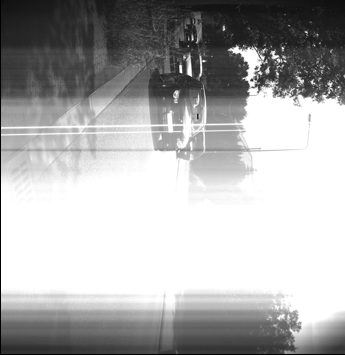
CCDs have slightly better light sensitivity and less noise than CMOS sensors. Higher light sensitivity provides better image in low light conditions. But CCDs are more expensive and can consume up to 100 times more power than CMOS, and sometimes when using a CCD sensor, a smearing effect may occur that interferes with the plate recognition process:
Nowadays, CMOS sensors are very close in terms of image quality to CCDs. At the same time, CMOS sensors reduce the overall cost of the camera because they contain all the necessary logic to build the camera and provide more integration capabilities and features than CCDs.
Sensor size: 1/3" or bigger (pixel size is more important).
Pixel size: 3.75 μm (micron) or bigger
Increasing the pixel size increases the image quality in low light conditions.
The size of a single pixel (x 1) can be calculated by dividing the sensor width in mm by the sensor width in pixels:
x 1= w/W
Where:
w is a sensor width in millimeters.
W is a sensor width in pixels.
Typical sensor sizes in mm are shown in the table below. It should be taken into account that the dimensions of specific sensors may differ from typical ones.
Sensor size |
Sensor dimensions (Width × Height), mm |
|---|---|
4/3" |
17,3 × 13,0 |
1" |
12,8 × 9,6 |
2/3" |
8,8 × 6,6 |
1/1,8" |
7,2 × 5,3 |
1/2" |
6,4 × 4,8 |
1/2,3" |
6,16 × 4,62 |
1/2,5" |
5,8 × 4,3 |
1/2,7" |
5,4 × 4,0 |
1/3" |
4,8 × 3,6 |
1/3,2" |
4,54 × 3,42 |
1/3,6" |
4 × 3 |
1/4" |
3,6 × 2,7 |
As an example, the calculation of the pixel size for a 1/3" sensor with a resolution of 1024x768:
x 1= 4.8/1024 = 0.00468 mm = 4.68 μm
Light sensitivity: 0.1 — 0.01 lux (in combination with a high-aperture lens).
Caution should be exercised with a camera with a claimed sensitivity below 0.003 lux, as this level of sensitivity requires additional signal processing. This significantly degrades the image quality and causes fast moving objects to blur, which as a result interferes with the recognition process.
IR Light Sensitivity: Availability of the Day/Night mode is recommended for round-the-clock recognition of license plates.
Dynamic Range: minimum 60 dB (an approximate contrast ratio is 1:1000).
Wide Dynamic Range (WDR): Activation of WDR is recommended. WDR significantly improves the image quality in high-contrast lighting conditions, which allows to capture details both in dark and bright parts of the field of view.
Lens🔗
If the camera is designed to allow lens interchangeability, it is very important to choose the right one. A lens designed to work with a 1/2" sensor is compatible with 1/2", 1/3" and 1/4" sensors, but it would not work with a 2/3" sensor.
If the lens is designed to work with a sensor smaller than the one installed in the camera, then the image will have black borders. If the lens is designed to work with a sensor larger than the camera's, then the field of view will be smaller than the capabilities of the lens, and part of the image will be left outside the sensor, creating a telephoto effect when the image looks enlarged.
Nowadays, cameras with the three most common types of lenses can be found:
Fixed lens: A lens with a constant focal length and therefore only one field of view available.
Varifocal lens: A lens with the configurable focal length that allows to get multiple fields of view. The field of view can be manually adjusted, but users then have to manually refocus the lens.
Afocal system (Zoom lens): Similar to a varifocal lens, afocal lens has a range of focal lengths and fields of view. However, the lens does not need to be manually refocused if the field of view is changed. Focus is maintained over the entire focal length range (for example, 6 to 48 mm). Moving the lens can be carried out manually or mechanized (with remote control). If the lens has the ability to zoom, then the magnification factor (multiplicity) corresponds to the ratio of the maximum focal length of the lens to the minimum.
Lens type: It is recommended to use lenses with configurable focal length (including afocal system) for the recognition of license plates.
Resolving power: The number of line pairs per millimeter must correspond to the physical resolution of the sensor.
When getting acquainted with the characteristics of a lens that can potentially be used for the recognition of license plates, it is necessary to take into account the number of line pairs per mm (LP/mm) that it is capable to project onto the sensor. For example, 5 dark and 5 light lines per mm form a resolution of 10 lines per mm, i.e. 5 pairs of lines per millimeter.
To calculate the exact number of pairs of lines per millimeter that the lens must provide visual distinction with a known sensor size, divide the sensor width in pixels by the sensor size in millimeter, then divide the result by two. Such a calculation can be represented as the formula below:
L mm= (W / w) / 2 = (1 / x 1) / 2
Where:
L mmis the number of pairs of lines per millimeter
W is the sensor width in pixels
w is the sensor width in millimeters
x 1is the size of a single pixel in millimeters
As an example, the calculation of LP/mm number for a 1/3" sensor with a resolution of 1024x768:
L mm= (1024 / 4,8) / 2 ≈ 107 pairs of lines per mm.
It should be taken into account that the resolving power may be affected by other factors. In particular, resolution may vary depending on different f-stop values (resolution is at its minimum when the iris is completely open). Minimum resolution value is provided in lens specifications. As the iris is closing, the resolution becomes higher (residual optical-system aberrations are reduced). It's important to keep in mind that focusing mistakes may reduce resolving power as well.
It's important to keep in mind that focusing mistakes may reduce resolving power as well.
Focal length range: Recommended ranges are 5-50 mm, 7-70 mm.
Aperture (f) number: 1.0, 1.2, 1.3, 1.4, 1.8.
Aperture control🔗
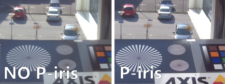
P-Iris. The recommended option, especially in non-constant lighting conditions. It allows avoiding diffraction (blurring of the image) effect and increasing the sharpness of the image, allowing video surveillance in a wide range of lighting conditions and distances — both in parking lots and on highways. This is achieved by automatically limiting aperture narrowing in strong light conditions. The limits for automatic control of the aperture additionally can be configured through the user interface of the camera.
For some cameras with P-iris, the user interface allows to configure the aperture opening on an index scale — from maximum to minimum. With this function, the iris position, which is set by auto adjustment for most lighting conditions, can be adjusted to the desired position.
DC-Iris. The allowed option. Comparing with P-iris, it only manages the exposure of the sensor. When DC-iris is opened, the sharpness is affected and auto-tuning of this image quality is not available.
Fixed or manual aperture. This option can only be used for surveillance under constant lighting conditions (e.g. indoor parking) when there is no need for constant aperture adjustment. The exposure in this case is set by adjusting shutter speed and AGC that is not as flexible as dynamic aperture tuning. A fixed aperture is set constructively during the manufacture of the lens, a manual aperture is set during lens adjustment and is not automatically adjusted during operation.
IR correction. Required to avoid overexposure if IR projector is used. Lenses of the kind usually have IR index in their marking.
Focal length🔗
To select a proper lens for a camera, it is needed to know the following values: sensor size, distance between the camera and the object and width of the object. Those three values are enough to calculate focal length of the lens in mm (or, if the focal length is available, calculate the width of field of view at set distance) using various CCTV and Lens Calculators.
Such calculators are available online (for example, on camera/lens manufacturers' websites).
Moreover, approximate focal length may be calculated using the following formula:
f = d * w / W
Where:
f f is a focal length in millimeters.
d is a distance between the camera and the object in meters.
w is a width of the sensor in millimeters.
W is a width of the object in meters.
Camera's angle of view is determined by focal length value. When calculating the angle of view, the following points must be borne in mind:
The shorter the focal length, the larger the angle of view, and vice versa.
The smaller the sensor size, the smaller the angle of view (for a lens with the same focal length).
The following table represents the correlation between angle of view and sensor size as well as focal distance of the lens. A standard CCTV Calculator was used for calculations.
Distance to the object (m) |
Object width (m) |
Sensor size |
Focal length (mm) |
Field of view (°) |
|---|---|---|---|---|
3 |
4 |
1/3 |
4 |
85 |
3 |
4 |
1/2 |
5 |
65 |
3 |
3 |
1/3 |
5 |
65 |
3 |
3 |
1/2 |
6 |
55 |
7 |
4 |
1/3 |
8 |
40 |
7 |
4 |
1/2 |
10 |
35 |
7 |
3 |
1/3 |
10 |
35 |
7 |
3 |
1/2 |
12 |
25 |
11 |
4 |
1/3 |
13 |
28 |
11 |
4 |
1/2 |
18 |
22 |
11 |
3 |
1/3 |
18 |
22 |
11 |
3 |
1/2 |
23 |
16 |
15 |
4 |
1/3 |
18 |
22 |
15 |
4 |
1/2 |
23 |
16 |
15 |
3 |
1/3 |
23 |
16 |
15 |
3 |
1/2 |
30 |
12 |
Depth of field🔗
Depth of field refers to the distance in front of and behind the focus point within which objects are sharp. The depth of field is an important value when recognizing license plates.
Depth of field is affected by the following three factors: focal length, aperture opening and distance from the camera to the object. A long focal length, long aperture opening or a short distance between the camera and the subject limiting the depth of field.
Many modern surveillance lenses are designed to provide a great depth of field over a wide range of focal lengths.
For some lenses it may be needed to adjust the depth of field manually. In this case, set the focal length first and only then configure the back focus. Adjust the back focus either in natural low light (evening or night) or artificially reduced daylight using an external neutral density filter (the ND filter usually places in front of the lens). Adjusting the back focus in bright daylight may cause an out-of-focus image at night. Adjust the back focus when the aperture is fully open (the maximum aperture is needed to reduce the depth of field to make back focus adjustment easier and more accurate). Sometimes it is difficult to precisely adjust the back focus, in which case it is recommended to set the focus to infinity.
Note that if the depth of field is shallow, the license plate number may not be recognized correctly or not at all. This is due to the fact that the application uses several adjacent frames received during the movement of the vehicle through the controlled area for recognition. With a shallow depth of field, the license plate can not be clearly recognized only in one sharp image, while in the rest of the frames it will be blurred.
Lenses with automatic iris (fixed and adjustable focal length) can have two settings:
Automatic or Auto Light Control (ALC), which controls the sensitivity of the automatic iris control circuitry to changes in light levels.
Level, which allows setting the average value of the iris.
For such lenses, it is recommended to set the medium value for the Automatic adjustment and configure the Level as follows: set the maximum value and point the camera so that the maximum amount of light enters the lens (it is strictly forbidden to point the lens directly to the sun as it will lead to sensor malfunction) and then cover the camera lens for 5 seconds. After opening the lens, the image should reappear. If this does not happen — repeat the adjustment.
Shutter speed🔗
Shutter speed (Exposure) is one of the critical parameters when recognizing license plates. It is highly recommended to use cameras with manual shutter speed control for license plate recognition.
It is important to keep in mind that too slow shutter speed result in the blurring effect of the license plate characters on the image. Moreover, while watching a video, they may seem clear, but when viewed frame-by-frame, distortions are clearly visible.
For each movement speed mode there is a range of recommended values which should be set for shutter speed depending on the maximum speed of vehicles in the control area.
Maximum vehicle speed in the control area (km/h) |
Shutter speed (sec) |
|---|---|
17 |
1/200 |
20 |
1/250 |
90 |
1/1000 |
130 |
1/1500 |
180 |
1/2000 |
In addition, if the horizontal camera rotation angle to the license plate plane exceeds 10°, it is recommended to halve the shutter speed, since the license plate image in this situation is blurring along several axes.
Infrared illumination🔗
To provide round-the-clock recognition in the area with changing lighting conditions, an infrared illumination (by means of either embedded or standalone IR projector) is required. In this case, it is necessary to select a camera with an infrared-sensitive sensor (so called day/night camera). The camera must be equipped with a lens with infrared correction (IR compensation). Marking of such lenses usually contains the "IR" index. As a result, an informative monochromatic image will be provided even for a poorly illuminated areas.
IR illumination range: Recommended value for license plate recognition is 850–880 nm. It has sufficient recognition distance and generates a comparatively low amount of visible illumination.
IR illumination mode: It is recommended to use IR projector in impulse mode when the illumination impulse is synchronized with global shutter operating mode. This provides more rational use of projector's energy resources, prolonging its service life and saving electricity.
Angle of illumination (if standalone IR projector is used): Should be the same as the camera angle of view. If illumination angle of IR projector is lower that camera angle of view, an exterior light source or well-lit object may get captured in the field of view making the shutter work under the average frame lighting value and thus lower the exposure (equal to forced decreasing of the camera sensitivity). Balancing illumination angle of IR projector and angle of view of the camera is especially important for long-distance surveillance when the camera works at the limit of its sensitivity.
Back focus and depth of field with IR lighting: Since IR light has a longer wavelength and lower refractive index than conventional light, the plane of the focused image is positioned slightly behind the plane of the image sensor.
ND filters🔗
When surveillance is carried out under changing lighting conditions (usually, outdoors), an overexposure may occur. In such cases, a required f-stop is achieved by combining the features of mechanic iris and a neutral density (ND) filter. This type of filter is also useful for minimizing the depth of field when adjusting the back focus or adjusting the auto iris level during the day.
There are built-in and external ND filters. It should be noted that the optical accuracy of ND filters is very important, because as the f-number increases, the resolving power of the lens must be maintained, which theoretically is at its maximum in the middle of the mechanical aperture setting range and decreases as the f-number increases/decreases (this is different from the depth-of-field effect). The possibility of the neutral-gray filter reducing the resolution of the lens has to be taken into account.
Filter properties may be specified in different ways:
ND*** and ***X indicate light blocking by how many times the filter attenuates the light.
*.* ND indicates the optical density number of the filter.
f-stop reduction value indicates the number of exposure compensation steps (aperture steps, f-number).
Light blocking |
Density |
f-stop reduction |
|
|---|---|---|---|
ND2 |
2X |
0.3 ND |
1 |
ND4 |
4X |
0.6 ND |
2 |
ND8 |
8X |
0.9 ND |
3 |
ND16 |
16X |
1.2 ND |
4 |
ND32 |
32X |
1.5 ND |
5 |
ND64 |
64X |
1.8 ND |
6 |
ND100 |
100X |
2.0 ND |
6 ⅔ |
ND256 |
256X |
2.4 ND |
8 |
ND400 |
400X |
2.6 ND |
8 ⅔ |
ND500 |
500X |
2.7 ND |
9 |
ND1000 |
~1,000X |
3.0 ND |
10 |
ND10000 |
~10,000X |
4.0 ND |
13 |
ND100000 |
~1,000,000X |
6.0 ND |
20 |
Filters can be combined to achieve the desired degree of light attenuation. For example, combining the ND8 and ND100 results in a filter with attenuation of 800 times.